
Project Documentation Requirements & the Importance of Project Handover Documentation
1. INTRODUCTION
This discussion of Project Documentation Requirements (PDR) sets forth a controlled and auditable process to identify all of the manuals, procedures, documents, drawings, databases, and indexes required for Installation, Hook-up, Commissioning, and Handover of Final Project Documentation to the Owner for safe and sustainable Operability and Maintainability of a typical Process Plant.
The PDR defines the minimum required documentation from an EPC Contractor to the Owner. The PDR lists the documents by type, format, and source, and identifies the partitioning of the documentation into specific categories.
It is recommended that the Contractor work jointly with the Project Leadership Team to develop a PDR compilation and completion schedule to track and ensure timely delivery of Final Project Documentation.
2. SCOPE
The scope of this PDR process document describes the planning, preparation, and compilation requirements, and the inclusion and development of the Master Document Register. The PDR includes the listing of project documentation deliverables and milestones, identifies early project delivery documentation for Installation, Hook-up, and Commissioning, and the required PDR delivery formats. The PDR describes the partitioning process and listing of technical documentation into the specific Project Documentation groupings.
2.1 KEY DOCUMENTATION
One of the criteria by which a project is evaluated as successful is the quality of Handover documentation. This article examines some of the more important aspects that should be considered as part of the Project Deliverables.
There is voluminous information generated during the life of a major project and, in order for the Client to access specific records, the Owner should consider establishing a Document Management System (DMS) at the initiation of the Project. Moreover, the DMS should be designed such that Project documentation from all sources (Pre-Final Investment Decision, Engineering, Procurement, and Construction (EPC) works, Project Handover and Close Out) is prepared in formats that facilitate easy import into the Owner’s DMS.
2.1.1 Term Definition
Key definitions concerning Project Documentation Requirements are provided below.
- As-Built Documentation: Redlined and/or marked-up information formally incorporated into new revisions of the original documents.
- Electronic Databases: Electronic tools used to organize information, e.g., a Document Management System (DMS): These are prepared to assist with sorting, arranging, querying, and reporting a large quantity of information (e.g., follow-up actions from Risk Assessment, Constructability Reviews, Non‑Conformance Register, Hazard Operability (HAZOP) and/or Hazard Identification (HAZID) outcomes, Engineering Design, Contract information, Vendor-supplied Equipment data etc.).
- Project Documentation Requirements: All technical documents, drawings, or electronic deliverables defined in the “Project Documentation Requirements” such as final project documentation (including As-Built deliverables) handed over by the EPC Contractor and its Subcontractors to the Project Leadership and Owner.
- Information and Knowledge: Information and knowledge may be contained in a document, drawing, or database in the form of electronic or hard copy data, figures, text, etc.
- Integrity-Critical Documents: Documentation that is required for hazard analysis, for developing operating procedures, required for training of personnel, and required for the basis of developing Company’s Process Safety Management Systems/Procedures, Operations & Maintenance (O&M) Strategy and Systems, particularly Asset Integrity Management Systems (AIMS), and Control of Work (COW) procedures.
2.1.2 Project Deliverable Requirement (PDR) Planning and Preparation
The planning and preparation of Project deliverable requirements typically should include workshops, schedules, and status meetings.
2.1.2.1 PDR Workshops
Because documentation requirements are often accorded low priority in the EPC phase of a major project, it is recommended that in addition to its inclusion in the Engineering, Procurement and Construction (EPC) Invitation to Bid (ITB) documentation, the Project Leadership and Contractor(s) hold a pre-bid PDR workshop and planning session to develop a clear understanding of the PDR and to establish the strategy, mechanism, the timing of the PDR handover phases, the tools to manage the compilation and, very importantly, review the formats for delivery of final documentation from Contractor(s) to the Owner. This strategy will ensure that the Project Documentation Handover requirements are adequately considered in the preparation of the EPC Contractor’s Cost and Implementation Schedule.
2.1.2.2 PDR Schedule
Given its importance for future operations and archiving of Project information and data, a PDR schedule should be developed jointly by the Project Leadership and Contractor at the initiation of EPC Works. The PDR schedule should define each deliverable and record its expected and actual delivery dates in a Master Document Register.
To ensure tracking of PDR Handover, Delivery Status Reports – detailing the progress of the project Handover documentation – should be issued monthly, with reports on the overall progress and status for the Contractor/Subcontractor deliverables by grouping, including:
- Specific project activities or milestones associated with PDR
- Scheduled and actual deliverables of early and final documentation
- Issues that might impact PDR schedules or milestones
- Other associated concerns
2.1.2.3 PDR Status Meetings:
PDR status meetings should be scheduled periodically between the Owner and Contractor to discuss the overall status of PDR and project activities affecting handover schedules. It is best practice to include progress on Project Handover Documentation in the EPC Contractor’s Monthly Project Report. This should be a permanent agenda item for the Owner-Contractor Monthly Progress Review Meeting in order to ensure parallel development of the PDR in alignment with the Owner’s expectations.
2.1.3 Project Deliverable Requirements
A brief overview of the PDR contents for each of the partitioned groups is discussed below. The PDR partitions the project documentation into eight (8) groupings of information. Each bucket contains specific recordkeeping content necessary to compile the final documentation.
2.1.3.1 Systems Turnover Packages
Each Systems Turnover Package will contain the System Descriptions for all identified systems to be installed, hooked-up, and commissioned. The Contractor will describe the system’s design basis, function, description, and controls, and detail any special considerations. Each system will be defined on Issued for Construction (IFC) Piping & Instrumentation Diagrams (P&IDs) and Process Flow Diagrams (PFDs), where appropriate.
There should also be information on the Mechanical Completion and Commissioning activities, Non-conformances, Deviations, Pressure Safety Valve (PSV) Certification, and Lifting Equipment Certifications. This section will also include the Instrumentation Data sheets, Control Systems data, Alarm management information, Process Safety System (PSS) information, Safety Instrumented Systems (SIS), Safety Integrity Levels (SILs), Rotating Equipment test reports, Vibration Baseline data, Equipment Vessel Installation reports (including QA/QC closure sheets for Vessels, Heat Exchangers, Columns, Heaters, etc., signed by the authorized Operations representative), Piping Isometrics, weld maps, and all installation activities. The documentation will be mainly in hard copy (i.e., original certificates, PSV data cards and lifting equipment and Installation reports).
It is readily seen that this level of documentation requires upfront agreement to avoid delays and disputes that disaffect final EPC Contractor payments. The following are typical contents of a System Turnover Package:
System Description, System Limits, Associated Systems, and Performance Standards
- System Description
- System Limits
- Associated Systems
- Performance Standards
Safety Assessment
- General Safety
- System Specific Safety
- Environmental Considerations
Completions
- Certificate of Mechanical Completion
- Index of Discipline Mechanical Completion Documentation
- Discipline Mechanical Completion Certificates
- Index of Check Sheets
- Index Reports for Outstanding and Completed Punch List Items
- Drawing List and Mechanical Completion (MC) Red Line Marked-up Drawings
- Non-conformance Reports/Technical Queries Status
- Boundary Drawings (Marked-up P&IDs)
- Pressure Safety Valves (PSV) Index and Original Certificates shall have the following minimum attributes:
- Tag Number
- Model number and Type
- Service Description
- Area Code
- Purchase Order (PO) number
- Manufacturer/Vendor (ensures traceability to the Vendor Documentation)
- P&ID Reference Number
- Datasheet Reference Number
- Calibration & Pressure Relief setting data
- Test Certificate Number and Date
- Factory Acceptance Test (FAT) and Site Acceptance Test (SAT) Reports
- Instrument Input/Output (I/O) lists
- Instrument Loop Check results
- Weld Maps should be available in the project Handover files but are generally too large to include in a System Turnover Package
- Hydrotest Records by Test Packs
- Line Flushing/Blowout documents certified by Operations
- Bolt Torqueing Records
- Preservation and Maintenance Records
- Alignment Records
- No-load Motor Voltage, Current and Vibration records
- Preservation and Maintenance Records
Commissioning Materials, Spares and Test Equipment
- Commissioning Materials
- Commissioning Spares
- Special Tools and Test Equipment
Commissioning Scope and Performance Test
- Index of Commissioning Completion Documentation
- Commissioning Scope
- Pre-Commissioning, Commissioning and Start-up procedure
- Commissioning Tests Records and Reports
- Commissioning Checklist status
- Commissioning Completion Certificate
- Performance Test data
Vendor Support
- Vendor Support Requirements
- Contingency Requirements
- Drawings/Vendor documentation
- As-built Drawings
- Vendor Drawings
- Vendor Data Sheets
It is highly recommended that the definition of all systems in a process plant and the contents of each System Turnover Package be agreed as early as possible in the EPC Phase so that the System Mechanical Completion could be easily tracked and certified, including agreement on Punch Lists, etc. Moreover, getting these protocols right will greatly enhance efficiency in the Pre‑Commissioning, Commissioning, and Start-up phases.
2.1.3.2 Operations and Maintenance Manuals
Operations and Maintenance (O&M) Manuals are central to training the Owner’s operating personnel in advance of the commencement of Commissioning and Start-up activities. Operation Manuals describe each system’s mode of operations and the Overall Plant Operating and Maintenance philosophy. In addition to O&M manuals, Owners sometimes procure generic and/or custom built Operator Training Simulator(s) to ensure that process Operators are well trained ahead of Start-up.
Experience has shown that fit-for-purpose O&M Manuals typically include:
General Description
- Plant Duty
- Listing of various Processes (Licensors) and Product Streams
- Design Basis for Plant Throughput
- Material Balance Information
- Description of Flow Parameters
- Utilities and Chemicals Requirements
- Vendor supplied Operations & Maintenance manuals (see typical Vendor supplied data/information later at 2.1.3.4 in this article)
Operating Conditions and Controls
- Process Description
- Operating Philosophy and Normal Operation
- Discussion of Process Variables
- Discussion of the Effect of Process Variables on Process Control and Product Quality
- Guidelines for Checking Process Conditions at the operating (control) panel and in the field, and making adjustments to process control parameters
- Discussion of Unit, System, and Plant Process Control, with emphasis on control loops
- Development and application of Process Trends to aid Operators
- Sampling and Laboratory Analyses and their application to process control
- Description of Electrical Systems and Equipment
- Description of Instrumentation
- Description of Utility Systems, including required inventories of chemicals or other special materials
- Equipment sparing philosophy
- Operation of Special Equipment, e.g., surge control for major centrifugal compressors
Plant Safety and Environmental Control
- Data Sheets for Pressure Safety Valves
- Data Sheets for Car Sealed Valves
- Cause & Effect Diagrams
- Emergency Shut Down (ESD) System description
- Safety Instrumented Systems Description (includes Safety Integrity Levels – SILs)
- Recommended Safety Instrumented System (SIS) testing schedule
- Instrument Alarms
- Alarm Management Protocol
- Selected Elements of the Process Safety Management System
- Fire Fighting and Protective Equipment
- Fire & Gas Control System
- Maintenance of Safety Equipment and Housekeeping
- Control of Work (COW) Procedures, e.g., Isolation, Purging, and Venting of Process Systems in preparation for safe work; Permit to Work (PTW); Lock Out Tag Out (LOTO), etc.
- Testing Schedules for Hydrocarbon content in Effluent Streams and levels of Air Particulates
- Testing Schedules for Noise (Decibels) at Plant Battery Limit
Major Equipment
- General: equipment selection process, equipment description and operations and maintenance instructions
- Equipment control philosophy and normal operation
- Description of design and data sheets for:
- Vessels
- Heat Exchangers
- Furnaces
- Pumps (centrifugal, reciprocating, rotary, etc.)
- Compressors
- Fans
- Special Equipment Summary and O&M instructions, e.g., Programmable Logic Controllers (PLC), equipment-mounted Vibration Monitoring equipment
- List of Instruments
Drawings
- Plot Plans
- Process Flow Diagrams (PFDs)
- Piping & Instrument Diagrams (P&IDs)
- Electrical One-lines
- Electrical Schematics
- Emergency Shut Down (ESD) Logic diagrams
- Cause and Effect diagrams
Standard Operating Procedures (SOPs)
- Special Control Procedures
- Proprietary Procedures or Techniques
- Initial Start-up Procedure
- Normal Start-up Operating Procedures
- Normal Shut-down Procedure
- Process Shutdown Procedure
- Emergency Shut-down (ESD)
- Start-up after Emergency Shut-down
- Black Start Procedure
- Other SOPs, e.g., Isolation, Purging, Venting; preparation of hydrocarbon containing equipment for safe maintenance activity
Standard Maintenance Procedures (SMPs)
- Maintenance Procedures for Systems and Equipment
- Recommended Preventive Maintenance Schedule
- Spare Parts List or References to Spare Parts Listing
- ESD Safety System Integrity
2.1.3.3 Fabrication, Installation and Verifying Documentation
Fabrication, installation and verifying documentation includes construction, manufacturing, installation, testing, reporting, and certification documentation required to demonstrate that construction, equipment, materials and fabricated systems and units are in compliance with applicable regulations and Invitation to Bid (ITB) specifications. The “Fabrication Records Books” (FRBs) are essentially a systematic buildup of fabrication documentation generated during the manufacturing/construction Phase. If the Project is being executed under ISO 9001:2015 guidelines, there will be copious documentation, but some salient points are noted below:
- Certificate of Conformance – Contractor confirms the requirements in the contract/purchase order for design, calculations, fabrication, installation, and testing have been met
- Material Traceability, Weld, and Non-Destructive Testing (NDE) documentation
- List of Certificates
- Calibration Certificates
- Pressure Safety Valve (PSV) Certificates
- Approval Certificates, e.g., ASME U-Stamp for Vessels
- Fire Protection Material Test Certificates
- Pressure Test Certificates per applicable Code
- Third-party (Vendor) Certificates
- Photos/Video Recordings of Structures and Equipment for archiving of special events during either plant construction or third party fabrication in offsite shops
These PDR sections also focus on capturing deviations occurring from design/fabrication requirements, specifications, etc., along with the reasons and the follow up actions taken to achieve “As-Built” status. The Fabrication and Installation data record major occurrences during the project fabrication and installation phases of the project. The data further provides the Owner with key As-Built information identifying Areas of Concern, e.g., difficult repairs, special rigging or tooling equipment requirements, and/or complex installation procedures for very heavy equipment such as large reactors that can weigh in excess of 300 tons.
Most importantly, the Fabrication and Installation documentation reflects the As-Built status of the installation.
2.1.3.4 Vendor Documentation
On large projects, Vendors supply major equipment on a subcontracted procurement basis with the EPC Contractor, who has the responsibility to install the equipment as part of the construction process. In some instances, Vendors may also be required to supervise and even install their equipment. Most certainly, Vendors play a very important part in the mechanical completion, pre‑commissioning, commissioning, and start-up of their packages and by extension the entire process plant. They also provide hands-on training for Owner personnel, both at their factories where witnessed tests take place and at the installation site.
It is, therefore, very important that Vendor Documentation be supplied in a form and of a quality that complements the overall Project Documentation Requirement. As a first step, Owners must ensure that the relevant procurement clauses in the EPC Contract reflect the Owner’s understanding of the value of such information. The Owner must also ensure that the EPC Contractor includes these clauses in each procurement subcontract so that all Vendor Documentation is supplied in the same format for easy importation into the Owner’s document management system.
Vendor Documentation would typically be contained in several volumes (binders) that include, but are not limited to, the following:
Introduction
- Index for all Volumes
- Suppliers Information (Purchase Orders, Test, Certificate, and Inspection Requirements
- Standards and Codes
- Sub-supplier Information (Purchase Orders)
- Detailed Index for each Volume – Exact contents of each volume by section and subsection to include document number, title, and revision
- Cross-reference between Supplier document numbers and equipment tag numbers. Cross-references for the following drawings/documents are required:
- Supplier/Vendor P&IDs and Project P&IDs
- Package General Arrangements (Layouts)
- All Data Sheets
- Package Operating and Maintenance Procedures
- Electrical One-lines and Block Diagrams
Description
- Equipment Location Details
- Equipment, Instrument, and Manual Valve Index
- Short Description of Total Package including Scope of Work
Procedures
- Transport and Handling (Shipment)
- Installation
- Mechanical Completion, Pre-Commissioning, Commissioning, and Start-up
- Mothballing Procedures (in the event there is a lag between installation at site and the commencement of commissioning activities)
- Supplier Service/Safety/Technical Bulletin, including Material Safety Data Sheets (MSDS)
Certificates
- Declaration of Conformity and Certificate of Conformance by Manufacturer
- Third Party Inspection Reports
- Load Testing Certification
- Certification of Lifting Equipment
- No-load Motor Data (Voltage, Current, Vibration)
- Fire Protection/Material Test Certificates
- Pressure Vessels Design, Manufacture/Test Certificates
- Equipment Calibration & Test Certificates, e.g., Factory Acceptance Test (FAT), Site Acceptance Test (SAT), Load Tests of turbo machinery, pumps, etc.
- List of Non-conformances and Deviations from Purchase Order (PO) Requirements
User’s Manuals
- Table of Contents – Information about Structure and Instructions for Use.
- Main Data for all Equipment (HSE, Process, Noise, Weight, Material Safety Data Sheets (MSDS), Technical Datasheets, Performance Curves, etc.). Main data typically include a list of all tagged equipment and instruments included in the package. Tag number, description, datasheet number, manufacturer’s name, type, model number, and location shall identify equipment and instruments on the list.
- FAT and SAT Test Reports with Associated Procedures and Completion Certificates
- Package Operating Instructions
- Recommended Start-up Spares, Two (2) years’ Spare Parts List, Spare Parts
Interchangeability List
- Cause and Effect Matrix
- All Associated Engineering/Vendor Drawings
2.1.3.5 Design Documentation
Design documents for all aspects of the Plant design define the design bases of the plant and they ensure that the design components fit together. When these documents are of Issued for Construction (IFC) quality, they are used as references by external regulatory agencies, equipment vendors and construction contractors. They are also of critical importance in the conduct of independent investigations which may be required if a process plant experiences major failure or fatalities.
This documentation is prepared during the detail engineering design activities and provides a listing of all major changes/deviations from the design basis considerations, but also the reasons and approvals behind the deviations. Also listed are any Areas of Concern that Operations should be aware of during facility Operations and Maintenance (i.e., areas of high stress, areas of potential high corrosion, and areas requiring frequent reviews and checks.)
During the execution of the contract, there is a systematic compilation of all design documentation records generated. On a major Contract, several volumes of Design Data would be compiled which typically reflect:
Design, Specifications, Procedures
- Design Basis
- Functional Codes, Standards and Specifications
- Functional Description of Control and Monitoring System and Software
- Project Design Criteria
- Design Philosophies
- Design/Engineering Studies
- Design Reports
- Environmental Parameters
- Criticality Classification
- Corrosion/Cathodic Protection Design
Process Flows/Diagrams Drawings and Datasheets
- Process Design Basis
- Flow Calculations to ensure Flow Induced Vibration (FIV) and Acoustic Induced Vibration (AIV) are considered to avoid premature piping failure. These calculations are of particular significance in large bore cryogenic piping systems, for example in an LNG Plant
- PFDs, P&IDs, HVAC Drawings
- Cause and Effect Diagrams/Shut-down Matrix
- Process/Equipment Datasheets
- Relief System Design and Design Basis
- Pressure Safety Valve (PSV) sizing Calculations & Vendor’s Calibration Reports
- Simulation Models, Dynamic, Static
- Flare Load calculations
Electrical Drawings/Diagrams/Datasheets
- Single-line Diagrams – Overall and Earthing (Grounding) Design
- Single-line Index
- Circuit Diagram
- Wiring Diagrams and Terminations
- Electrical Schematic Diagrams
- Electrical Interconnection Information
- Electrical Arc Flash Calculations
- Level Diagram, Telecom
- Telecom Network Schedule
- Area Location Drawings
- Electrical – Analyses, Studies, Reports
- Electrical Datasheets
- Short Circuit Analysis
- Protection Relay design and test results
- Selectivity Analysis/Relay Coordination Study
- Electrical Load Study
- Load Flow Calculations
- Power System Dynamical Calculations
- Calculation of Harmonic Voltages and Currents
- Capacity Test Report for Emergency Generators
- UPS Battery Test and Load Test Reports
- Telecom – Analyses, Calculations, Studies, Reports
Instrumentation Drawings/Diagrams/Documents
- Instrumentation/Telecommunications Earthing (Grounding) Distribution Schematic Diagram
- Pneumatic/Hydraulic Hook-up Drawings
- Instrumentation/Telecomm Interconnection Diagrams
- Loop Reports/Drawings
- System Control Graphical Reports or Diagrams to Determine Logic Control and Shutdown Functions
- Logic Sequence Diagram/System Control Diagrams
- Instrumentation Calculations
- Instrument Tie-in Drawings and Work Packages
Piping Drawings/Plot Plans/Layouts
- Hook-up Drawing (Module)/Tie-in Drawings
- General Arrangement/Layout/3D CAD Views of HVAC, Piping, Structural Steel and Mechanical, Installations, Packaged Units
- Layout Drawings/3D model Isometric Views (Scope to be Agreed Upon)
- Location Drawings (Plot Plans)/3D CAD Views
- Inspection Isometrics
- Isometric Drawings for Piping, HVAC, Heat Tracing, etc., including Stress and 3D CAD Models
- Inspection Drawing Reports for Vessels Tanks, Heat Exchangers, etc., and 3D Output, Raster Graphic Reports
- Piping Stress Reports Including Calculations
- Underground Drawings
- Cathodic Protection
- Piping – Analyses, Calculations, Studies, Reports
Structural Drawings/Diagrams/Documents
- Structural Arrangement Drawings
- Structural Fire Protection Drawings
- Structural Steel and Outfitting Steel Drawings
- Structural Steel Detail Drawings
- Pipe/Ducting Support Drawings
- Foundation Drawings
- Structural Analysis and Calculations
- Final Weight Reports
- Structural Analysis Design Reports
Heating Ventilation & Air Conditioning (HVAC)
- Analyses, Calculations, Studies, Reports
- Numerical Analysis
- Heating and Cooling Capacity Calculations
- Ventilation Air Volumes
- Pressure Drop Calculations
- Sound Level Calculations
- Calculation for Air Supply/External Devices
HSE Analyses, Calculations, Studies, Reports
- Safety – Analyses, Calculations, Studies, Reports (including Quantitative Risk Assessment (QRA)
- Safety Instrumented System (SIS) design and protocol
- Safety, Integrity, and Functionality of Design, e.g., Safety Integrity Levels (SILs)
- Firewater Pressure Drop Calculations (PipeNet or PipeCalc or other approved software)
- HSE Studies as required by authorities, including Certificate of Environmental Clearance that would contain data on Atmospheric Emissions, Noise Levels in Plant and at Plant Fence line, etc.
- HAZOP/HAZID Studies
- Acoustic/Thermal Insulation and Fire Protection Plans
- Fire Water System design & Drawings
- Fire and Gas System and control design data and protocol
- Fire Protection Drawings
- Escape Route Drawings
- Material Safety Data Sheets (MSDS)
- Process Historian to facilitate easy retrieval of process data or to construct process trends for efficient and safe process operation
2.1.3.6 Engineering Databases
The contents of the engineering databases will be transferred from the Contractors as one final delivery with all Subcontractors and Supplier/Vendor information integrated. The final delivery format will be by native format in a Microsoft database. Engineering database indexes may include:
- Master Rotating Equipment List with Equipment Tag Numbers
- Master Stationary Equipment List with Equipment Tag Numbers
- Equipment Spares Listing, including cross-reference to minimize surplus warehouse inventory
- Piping Line Index
- Instrument Index
- Instrument Index Cable Index
- Fire and Gas Index
- Electrical Consumer Index
- Telecommunications Field Index
- Miscellaneous Electrical Equipment Index
- Motor Control Center (MCC) Index
- Programmable Logic Controller (PLC) Index
- Critical Pipe Line Index (e.g., special alloys)
- Lubrication Index
- Pipe Support Index
- Alarm Management Index
- Manual Valve Index
- Control Valve Index
- Pressure Safety Valve (PSV) Index
- Piping Isometric Drawing Index
- General Arrangement Drawing Index
- Foundation and Steel (Civil Engineering) Index
- Plant Historian Database (PHD): This is a key requirement for process engineers and other operating personnel to investigate trends and make corrective adjustments to plant operations. In the event of a major failure, the PHD facilitates the retrieval of information to conduct the appropriate level of investigation rigor.
2.1.3.7 Emergency Response Documents
Emergency Response Documents could include, but are not limited to, the following:
- Plant Emergency Response Manual (Plan)
- Black Start Procedure
- Emergency Shut down
- Cause and Effects – Safe Charts
- Heating Ventilation and Air Conditioning (HVAC)
- Arrangement/Machinery Arrangement and Lifesaving Equipment
- Hazardous Area Classification – Plan and Elevation
- Fire Fighting Equipment, Fire and Gas System Layout
- Fire and Gas Control System Operation
- Relevant Process Flow Diagrams/Piping & Instrumentation Diagrams (PFDs/ P&IDs)
- Safety Equipment location and operation
2.1.3.8 Performance Test Data
The type and extent of Plant Performance Testing is typically driven by the project specifications or the EPC contract. A successful Performance Test – when accepted by the Owner – is also usually linked to a key progress payment milestone and is the final test prior to handover to and acceptance by the Owner.
The requirements for a process plant Performance Test are spelled out in great detail in the EPC Contractor’s Scope of Work. The Performance Test is normally conducted at full-load operation for a predetermined period of time and requires significant planning and coordination in order to achieve stable test conditions to allow the Performance Test to proceed.
The test team collects the necessary data and runs them through the facility correction model to obtain preliminary results. Usually within a day, a preliminary test report or letter is generated to allow the Owner to declare Substantial Completion and commence commercial operation.
The results from the analysis of all Plant data and product quality are usually available within a couple of weeks, allowing the final Performance Test Report to be compiled and submitted to the Client. This usually takes the form of a lengthy presentation by the EPC Contractor to the Owner and the handing over of all test data and corresponding analyses in a hard copy and as well in the approved electronic form.
2.1.4 Final As-Built Documentation
The Contractor must certify that all Final Documentation in each of the foregoing areas reflects the As-Built status of the facility by ensuring all changes – which occurred during the Installation, Hook-up, and Commissioning – are captured and updated in the final Project Handover Documentation.
Final Documentation delivery will be formally submitted by transmittal with accompanying indexes, compiled in accordance with the PDR categories, and in correct file formats complying with agreed delivery schedules and will replace all previous deliverables where changes have been made.
2.1.4.1 Electronic Project Delivery Documentation
All drawings and technical documents delivered to the Owner will be in electronic format as shown below:
- PDF format, used exclusively for viewing only,
- Native original format (e.g., MS Office formats, AutoCAD drawings, etc.)
USB or external portable hard drives are the preferred transfer media for electronic deliverables, which should be seamlessly transportable into Owner’s Document Management System (DMS)
2.1.4.2 Electronic Prepared Documentation
Compiled documents such as Manufacturer Record Books and Fabrication Record Books are to be delivered in PDF format in addition to the hard copy.
The Owner normally requests a single document in PDF format with bookmarking for ease of searching and retrieval functionality. Ideally, this should be done to support the operating requirements of the Owner’s Document Management System (DMS).
2.1.4.3 Project Deliverability Requirement: Final Delivery Format
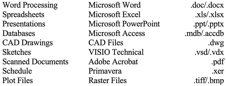
Only certain document file formats are acceptable as project documentation. These file formats include the following:
Table 1
Sample of Document Type Electronic File Formats
This table does not contain all possible associated or supported file types.
3. CONCLUSION
Delivering best-in-class Project Documentation Requirement (PDR) is not a task to be underestimated. Care should be exercised in the Front End Loading (FEL) phase of the Project being contemplated. Determining the type and content of Handover Documentation is a Value Improving Practice (VIP) that requires considerable discussion between the Project Team and the Owner. At the same time, the Owner should ensure that the Project Organization has the requisite number of personnel experienced in this important, but often overlooked, area of major Project execution.
Once there is alignment between the Project and the Owner, the particular specifications of the agreed PDR must be included in the Invitation to Bid (ITB) documentation for Engineering, Procurement, and Construction (EPC) Works and emphasized during ITB Clarification meetings that take place before bids are received by Owner. This will ensure that misalignment between the Owner’s expectations and the Contractor’s understanding of its responsibility is minimized.
The EPC ITB should require the Contractor to include a detailed documentation plan and schedule, which would be accorded appropriate weighting for Bid Evaluation. It should also be included in the Contractor’s Work Breakdown Structure (WBS) for the EPC Works.
During the execution of EPC works, the Project Team and the Owner should ensure that the PDR deliverables are being progressed to ensure achievement of the PDR Schedule Milestones. This aspect cannot be overemphasized, as the author has seen several Projects fail to incorporate the guidelines in this article, with the predictable outcome of disputes that require much time and many resources to resolve. Getting PDR right contributes greatly to the safe and sustainable commercial operation of Process Plants.
About the Author
S. Andrew McIntosh is a Senior Principal with Long International and has nearly 50 years of engineering, construction, onshore and offshore oil and gas operations, and management consulting experience. He has extensive international greenfield and brownfield project development and execution experience in diverse areas such as refinery, petrochemical, offshore oil and gas, LNG, oil and gas pipelines, and ferrous metallics projects ranging from US$20 million to US$1.8 billion. Before joining Long International, Mr. McIntosh served as President of The Natural Gas Company of Trinidad and Tobago. He also served as a Senior Operations Advisor, Vice President – Operations, and Vice President – Technical Services for several international energy companies. Mr. McIntosh has extensive experience in the development of Project Management and Project Execution Plans and Procedures, Stage Gate processes for Project Development, and the analysis and resolution of engineering and construction claims involving disputed change orders, schedule delay, and loss of productivity claims. Mr. McIntosh is based in Cascade, Port-of-Spain, Trinidad and can be contacted at amcintosh@long-intl.com and (868) 374-7717.
Copyright © Long International, Inc.
ADDITIONAL RESOURCES

Articles
Articles by our engineering and construction claims experts cover topics ranging from acceleration to why claims occur.
MORE

Blog
Discover industry insights on construction disputes and claims, project management, risk analysis, and more.
MORE

Publications
We are committed to sharing industry knowledge through publication of our books and presentations.
MORE