February 9, 2026
Process Plant Terminology Part 3: Typical Fluid Flow Processes
This is the third blog post in a nine-part series that provides layman’s descriptions of process engineering terminology commonly encountered when describing industrial processes and associated equipment. The terms described herein can be found in use across a wide range of processing and manufacturing industries, including oil and gas, refinery, petrochemical, chemical, mining and mineral, wastewater treatment, and power generation industries.
The first post provided an overview of the various drawing types that are used to depict industrial processing and manufacturing plants, while the second post discussed general processing and manufacturing plant terminology. Posts three through nine discuss common unit operations and processing equipment typically found in industrial processing and manufacturing plants, with this third post specifically discussing fluid flow processes.
Fluid flow processes involve the transportation of a fluid from one point to another and are typically driven by pressure differences in the fluid, with fluid flowing from points of higher to lower pressure. Common fluid flow process elements include Piping, Valves, and Fittings (PVF); ducting and turning vanes; pumps; fans; and compressors.
Piping, Valves, and Fittings (PVF): PVF refers to the piping or tubing, valves, and fittings that are components of typical piping systems. Typical materials of construction for piping systems (which are specified for a given service based on pressure ratings, chemical compatibility with the fluid being transported and ambient conditions, and cost considerations) include iron, steel, stainless steel, copper, and various plastics (PVC, CPVC, PEX, ABS, HDPE, etc.).
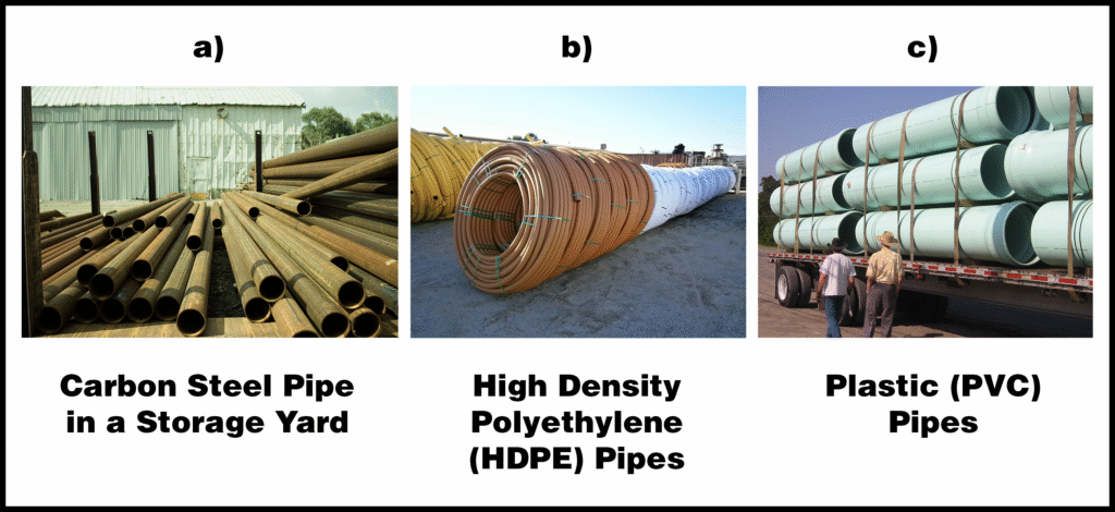
- Piping: A pipe is a hollow tube used to convey a fluid, and is commonly specified by its diameter, wall thickness (schedule), length, and material of construction. Individual pieces of piping are either welded, glued, or threaded together using fittings to form a piping network. Piping is typically supported from below or hung from above using pipe supports and clamps. Piping systems may be insulated to prevent heat loss from the fluid. Typical types of piping are shown below in Figure 1.
Figure 1: Typical Types of Piping1
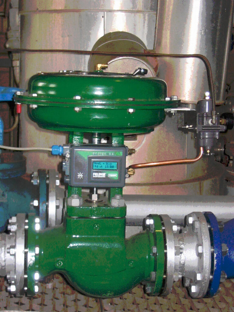
- Valves: Valves, which are devices that introduce pressure drop to control flow through a piping system, are typically one of two types: 1) on/off or 2) throttling. On/off valves (e.g., ball valves, also known as ¼-turn valves, and gate valves) are used to stop flow completely, whereas throttling valves (e.g., globe valves and needle valves) are used to adjust flow rates to desired values. Valves can be operated either manually (by hand) or automatically (by digital control systems). Control valves (automatic valves) utilize transducers, which can be either electric or pneumatic, to convert electronic control signals to valve actuator movement. Typical examples of valves are shown below in Figure 2 (ball valve), Figure 3 (globe valve), and Figure 4 (control valve).
Figure 2: Cut-Away View of a Ball Valve (On/Off Valve)2
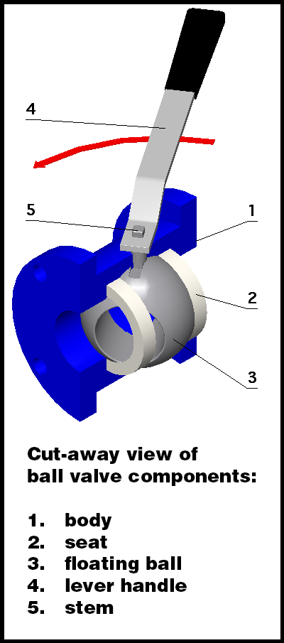
Figure 3: Cut-Away View of a Globe Valve (Throttling Valve)3
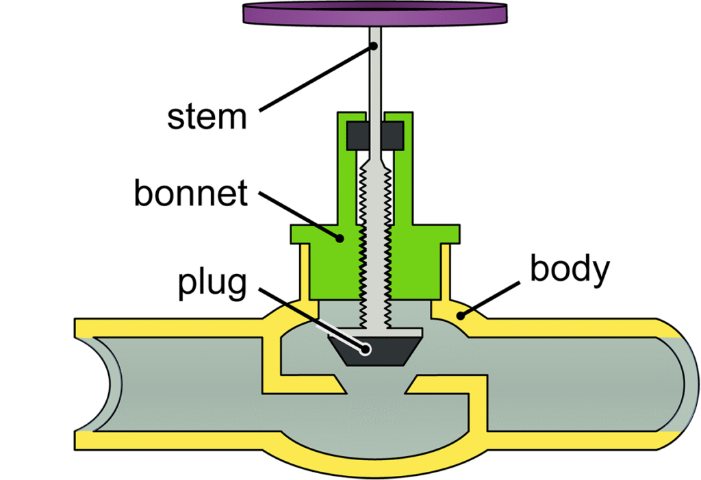
Figure 4: Typical Control Valve: Globe Valve with Pneumatic Actuator4
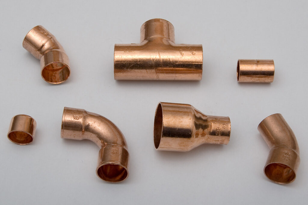
- Fittings: Typical pipe fittings include tees, 90° elbows (ells), 45° elbows, caps, plugs, reducers or expanders, unions, and couplings. Fittings are typically either welded, glued, or threaded to lengths of piping to form piping networks. Figure 5 below shows various types of typical copper pipe fittings.
Figure 5: Typical Copper Pipe Fittings5
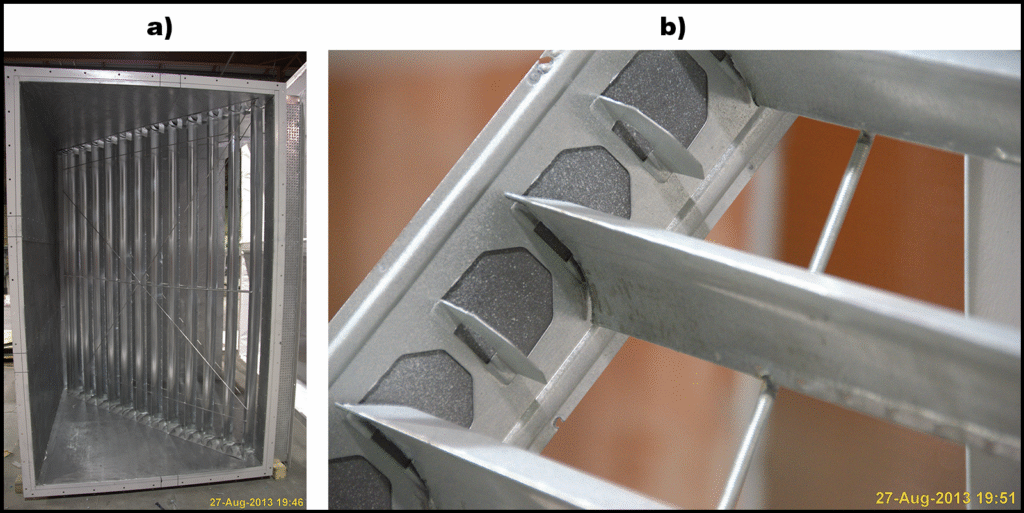
Ducting: Ducts are conduits used to convey gaseous fluids (typically air or flue gases). Like piping systems, ducting systems are formed by connecting individual pieces of ducting together using specialized fasteners or clips and then sealing the joints with mastic or tape to prevent leakage. Ducting systems typically contain dampers (analogous to valves in a piping system) to control flow rates either manually or automatically with the use of a transducer. Ducting systems may also employ turning vanes to minimize pressure drop associated with changes in flow direction and to improve velocity uniformity. Ducting systems may be insulated to prevent heat loss from the gas. Typical examples of ductwork components are shown below in Figure 6 (ducting), Figure 7 (damper), and Figure 8 (turning vanes).
Figure 6: Typical Ductwork6
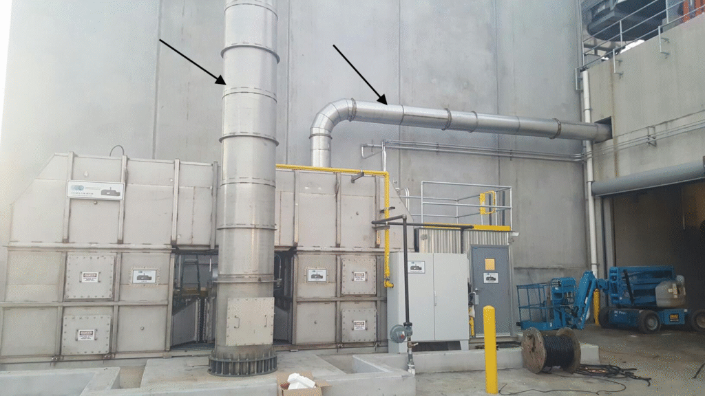
Figure 7: Ductwork Damper and Actuator7
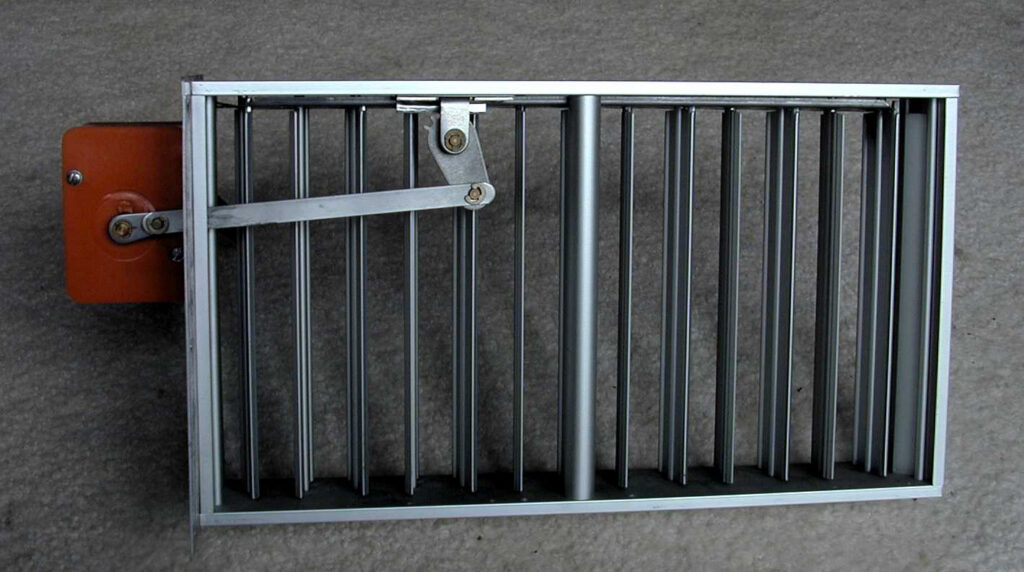
Figure 8: Typical Turning Vane Configuration8
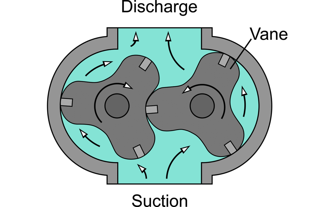
Pumps: Pumps are motor-driven devices that move fluids (typically liquids or slurries) through piping systems by using mechanical energy to increase fluid pressure. Pumps can be one of two types: 1) centrifugal pumps or 2) positive displacement pumps. Centrifugal pumps utilize impellers to impart kinetic energy to the fluid to increase pressure as shown below in Figure 9, while positive displacement pumps physically displace a characteristic volume of the fluid to increase pressure as shown below in Figure 10. Pump speed can be controlled using Variable Frequency Drives (VFDs), which vary pump motor electrical frequency and/or voltage based on inputs from digital control systems to achieve desired motor speeds and the resulting fluid flow rates.
Figure 9: Cut-Away View of a Centrifugal Pump9
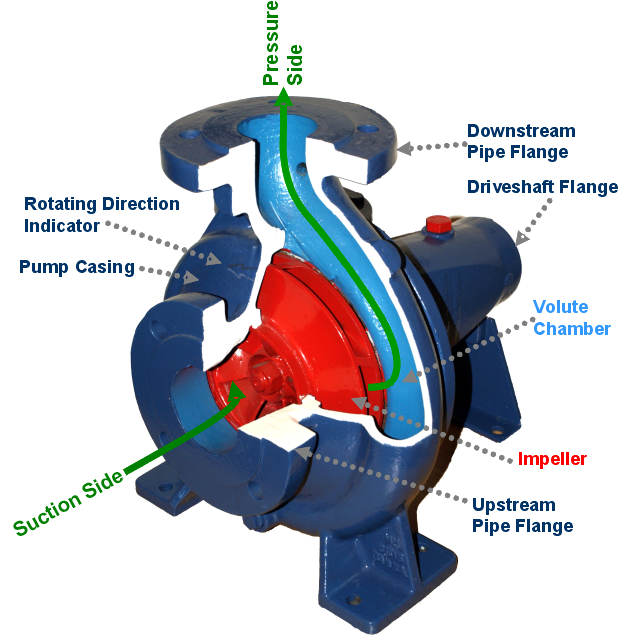
Figure 10: Cut-Away View of a Positive Displacement (Lobe) Pump10
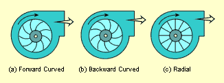
Fans: Fans are motor-driven devices that move gaseous fluids (typically air or flue gases) through ducting systems by using mechanical energy to increase fluid pressure. Fans are analogous to centrifugal pumps in that they impart kinetic energy to the fluid by using an impeller (fan blades, which can be either radial or curved), and the fan speed (and thus fluid velocity) can be controlled by a VFD. Fans typically cause only minimal pressure increases in the fluid when compared to compressors (see next section). An illustration of a typical fan and a cut-away showing the various types of fan blade configurations are shown below in Figure 11 and Figure 12, respectively.
Figure 11: Typical Fan11
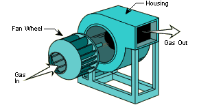
Figure 12: Cut-Away View of a Fan Showing Typical Fan Blade Configurations12
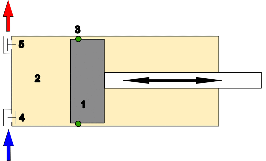
Compressors: Compressors are motor-driven devices that move gaseous fluids through piping by using mechanical energy to increase fluid pressure by decreasing the volume of the gas (i.e., by compressing the gas). Compared to fans that result in only minimal pressure increases in the gas, compressors are capable of significantly increasing the pressure of the gas, in some cases up to several thousand pounds per square inch (psi) if multiple compressor stages are employed. Like pumps, compressors can be categorized as either centrifugal (dynamic) or positive displacement (rotary and reciprocating), as shown below in Figure 13, and compressor speed (and thus fluid pressure) can be controlled by a VFD. Figure 14 below shows a cut-away view of a typical positive displacement compressor.
Figure 13: Types of Compressors13
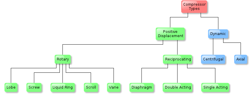
Figure 14: Cut-Away View of a Positive Displacement (Reciprocating) Compressor14
1 “Pipe (fluid conveyance),” Wikipedia: a) “Carbon Steel Pipe in a storage yard” by Paul Goyette under CC BY-SA 2.00, b) “High Density Polyethylene (HDPE) Pipes” by GordonJ86 under CC BY-SA 4.0, c) “Plastic (PVC) pipes” by Shah Rahman, public domain. Accessed November 23, 2025.
2 “Cut-away view of ball valve components: Body Seat Floating ball Lever handle Stem” by Ruben Castelnuovo under CC BY-SA 3.0, accessed November 23, 2025.
3 “Internal parts of a typical globe valve” by Petteri Aimonen, public domain, accessed November 23, 2025.
4 “Globe control valve with pneumatic diaphragm actuator and ‘smart’ positioner which will also feed back to the controller the actual valve position” by User A1 (talk) under CC BY-SA 3.0, accessed November 23, 2025.
5 “Copper pipe fittings” by Torsten Bätge under CC BY-SA 3.0, accessed November 23, 2025.
6 Adapted from “Ducts for air pollution control in a 17000 standard cubic feet per minute regenerative thermal oxidizer (RTO).” by Combustion2016 under CC BY-SA 4.0, accessed November 23, 2025.
7 “An opposed-blade, motor-operated zone damper, shown in the ‘open’ position.” under CC BY 2.5, accessed November 23, 2025.
8 “Turning vanes,” Wikipedia: a) “Turning vanes inside of large ductwork” by Achim Hering under CC BY-SA 3.0, b) “Turning vane close-up” by Achim Hering under CC BY-SA 3.0. Accessed November 23, 2025.
9 “Cutaway view of centrifugal pump” by Fantagu, public domain, accessed November 23, 2025.
10 “Lobe pump internals” by Jahobr under CC0, accessed November 23, 2025.
11 “Figure 1: Components of a centrifugal fan” linked by mbeychok, public domain, accessed November 23, 2025.
12 “Figure 3: Centrifugal fan blades” linked by mbeychok, public domain, accessed November 23, 2025.
13 “A taxonomy of different types of gas compressors.” by Zonination under CC BY-SA 3.0, accessed November 23, 2025.
14 “Reciprocating compressor function” by Yyy under CC BY 2.5, accessed November 23, 2025.
ADDITIONAL RESOURCES

Blog
Discover industry insights on construction disputes and claims, project management, risk analysis, and more.
MORE
Articles
Articles by our engineering and construction claims experts cover topics ranging from acceleration to why claims occur.
MORE

Publications
We are committed to sharing industry knowledge through publication of our books and presentations.
MORE
RECOMMENDED READS
Project and Construction Management Terminology
This post is part of a series defining industry terminology. This post addresses project and construction management.
READ
A Tale of Two Claims: Same Contract, Two Fates
The success of a claim often hinges not on what happened in the field, but how it was documented, analyzed, and communicated.
READ
The Role and Benefit of a Consultant in a Construction Project: Part 1
This is the first blog post in a two-part series on the role and benefit of a construction consultant.
READ