
December 9, 2025
Process Plant Terminology Part 1: Typical Drawing Types
This is the first blog post in a nine-part series that provides layman’s descriptions of process engineering terminology commonly encountered when describing industrial manufacturing processes and associated equipment. The terms described herein are used across a wide range of processing and manufacturing industries, including oil and gas, refinery, petrochemical, chemical, mining and mineral, wastewater treatment, and power generation industries.
This first post provides an overview of the various drawing types that are used to depict industrial processing and manufacturing plants. The second post will discuss general processing and manufacturing plant terminology, and posts three through nine will discuss common unit operations and processing equipment typically found in industrial processing and manufacturing plants.
Process Plant Drawing Types
Industrial process flows, associated equipment, and connections among various pieces of equipment in industrial processing and manufacturing plants are typically illustrated in the following types of drawings:
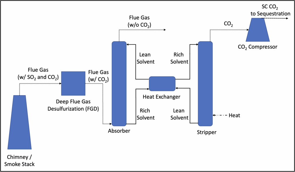
Block Diagrams: Block diagrams provide a high-level overview of the process and, as the name suggests, use blocks to depict major unit operations (the building blocks of industrial plants) and processing equipment (e.g., reactors, processing vessels, storage tanks, etc.). Block diagrams, which are typically accompanied by a high-level process description, show the main process flow streams (e.g., piping and ducting) between the various blocks, but they lack further detail regarding piping, instrumentation, or operating conditions. Figure 1 below shows an example of a typical block diagram.
Figure 1: Example Block Diagram (Post-Combustion Carbon Capture System)
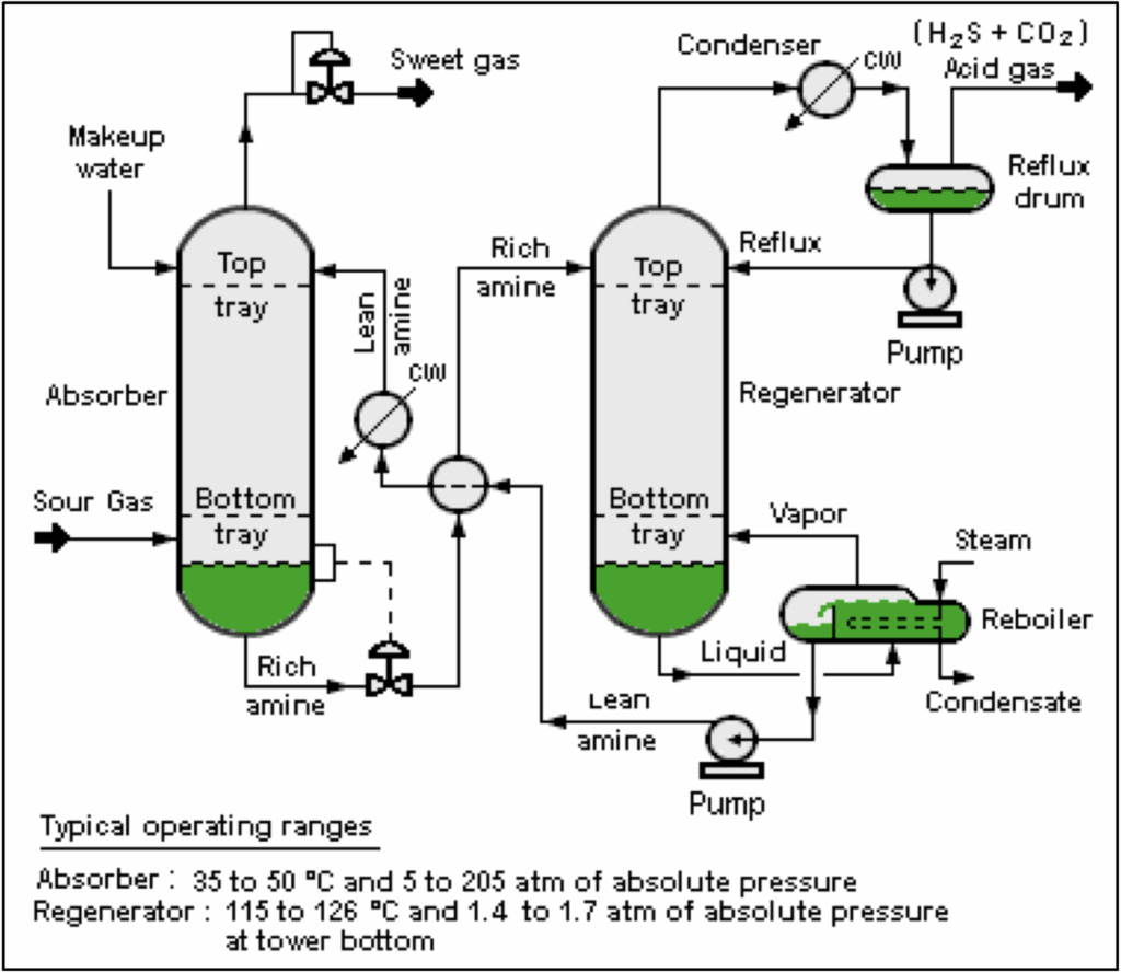
Process Flow Diagrams (PFDs): PFDs are more detailed than block diagrams. They may use either blocks or equipment symbols to illustrate the process, they show the process flow in greater detail than block diagrams, and they may indicate basic control points such as pumps and valves. PFDs are typically accompanied by a basis-of-design narrative, which describes the overall process design, including the functionality and requirements of the major equipment. PFDs may indicate typical operating conditions (e.g., temperature, pressure, flow rate, and chemical compositions), or they may be accompanied by a stand-alone stream table that includes this information. An example of a typical PFD is shown below in Figure 2.
Figure 2: Example Process Flow Diagram (Amine Treatment Plant)1
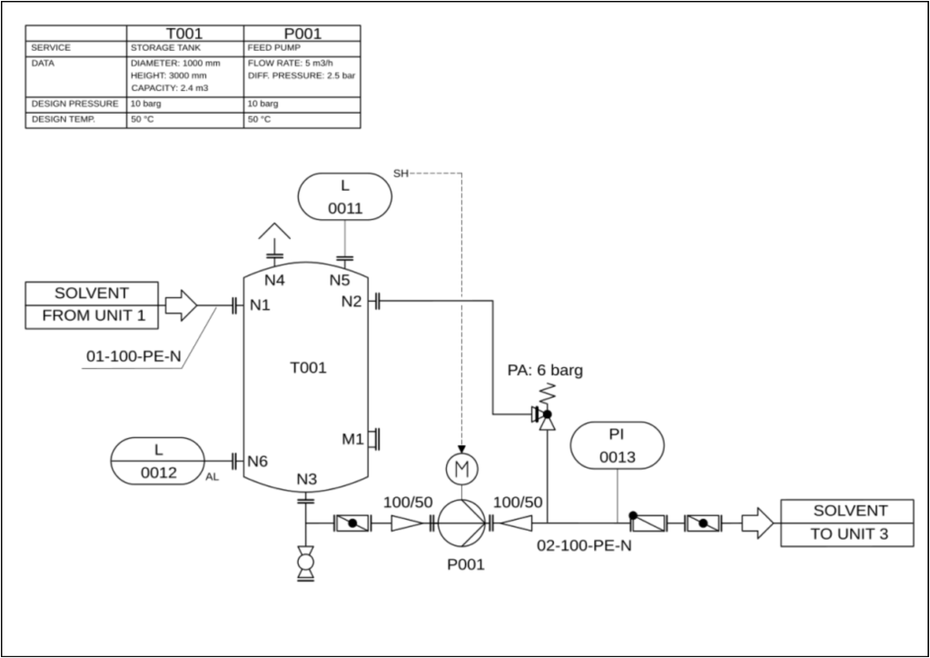
Piping and Instrumentation Diagrams (P&IDs): P&IDs are detailed schematics of the industrial process that build upon and enhance the PFDs to depict every detail of the process, including all ancillary equipment, instrumentation (e.g., sensors), control elements (e.g., control valves and variable-speed pumps), and feedback control loops. P&IDs are typically accompanied by several documents including line lists, equipment lists, and the control narrative. Line lists typically specify operating conditions, pipe size, and material of construction for all piping lines, while equipment lists typically contain equipment specifications such as sizing information, operating requirements, and materials of construction for all equipment. The control narrative contains a detailed description of the process and control strategies (e.g., feedback loops) as well as proper operational responses to off-nominal conditions. An example of a typical P&ID is shown below in Figure 3.
Figure 3: Example Piping and Instrumentation Diagram (Solvent Storage Tank)2
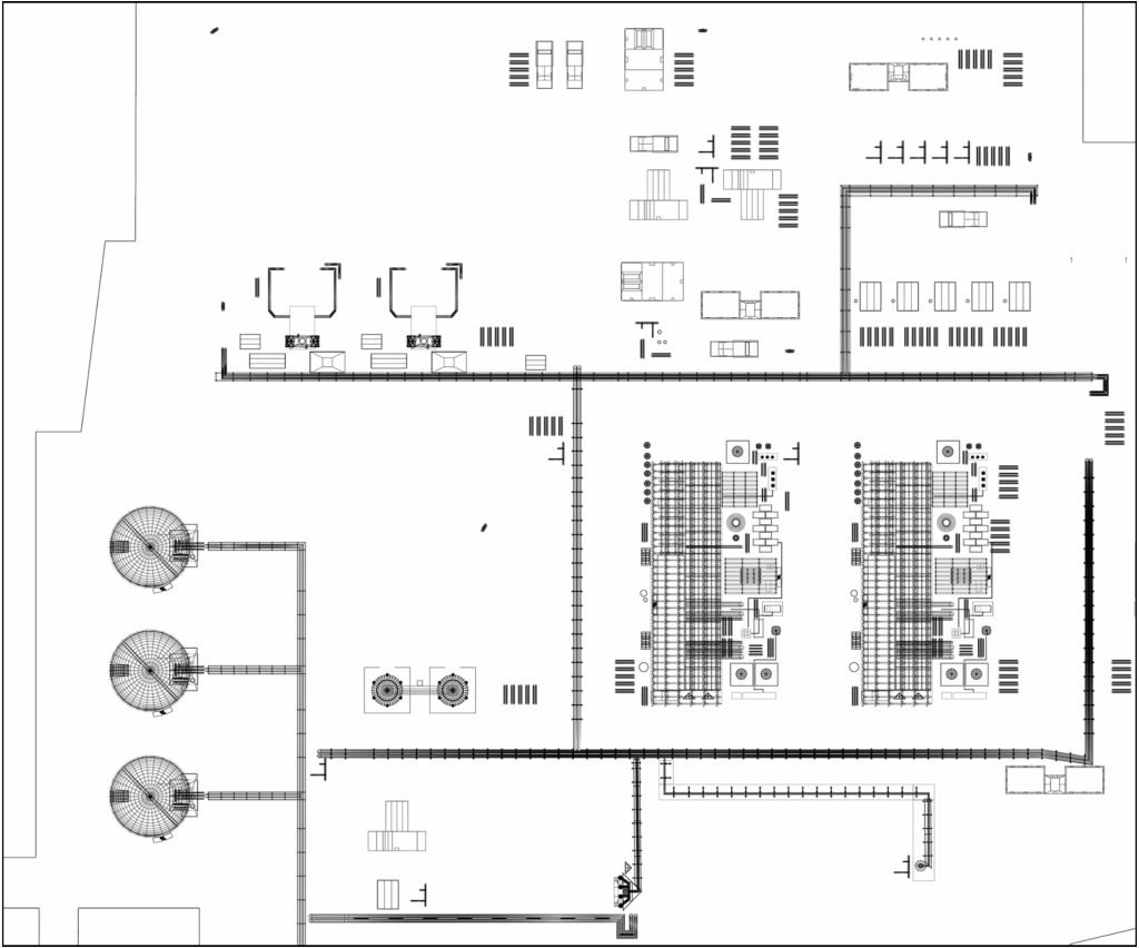
General Arrangement Drawings (GAs): GAs comprise plan (top-down-view) drawings, elevation (side-view) drawings, and appropriate section drawings that depict, to scale and with critical dimensions shown, the layout and arrangement of the processing or manufacturing plant components. GAs are useful for optimizing plant layouts to minimize both capital and operating costs, and for planning access to critical equipment and plant areas to facilitate efficient operations and maintenance activities. Figure 4 below shows an example of a typical GA drawing.
Figure 4: Example General Arrangement Drawing (Liquefied Natural Gas Plant)
1 “Flow diagram of a typical amine treating process used in industrial plants” by Mbeychok under CC BY-SA 3.0, accessed November 23, 2025.
2 “Piping and instrumentation diagram of pump with storage tank. Symbols according to EN ISO 10628 and EN 62424.” by Con-struct under CC BY-SA 3.0, accessed November 23, 2025.
ADDITIONAL RESOURCES

Blog
Discover industry insights on construction disputes and claims, project management, risk analysis, and more.
MORE

Articles
Articles by our engineering and construction claims experts cover topics ranging from acceleration to why claims occur.
MORE

Publications
We are committed to sharing industry knowledge through publication of our books and presentations.
MORE
RECOMMENDED READS
Project and Construction Management Terminology
This post is part of a series defining industry terminology. This post addresses project and construction management.
READ
A Tale of Two Claims: Same Contract, Two Fates
The success of a claim often hinges not on what happened in the field, but how it was documented, analyzed, and communicated.
READ
The Role and Benefit of a Consultant in a Construction Project: Part 1
This is the first blog post in a two-part series on the role and benefit of a construction consultant.
READ