
January 19, 2026
Process Plant Terminology Part 2: General Terms
This is the second blog post in a nine-part series that provides layman’s descriptions of process engineering terminology commonly encountered when describing industrial processes and associated equipment. The terms described herein are used across a wide range of processing and manufacturing industries, including oil and gas, refinery, petrochemical, chemical, mining and mineral, wastewater treatment, and power generation industries.
The first post provided an overview of the various drawing types that are used to depict industrial processing and manufacturing plants. This second post discusses general processing and manufacturing plant terminology, while posts three through nine will discuss common unit operations and processing equipment typically found in industrial processing and manufacturing plants.
Material Phases
Process flow stream descriptions typically indicate the phase of the material being processed. It is important to note that flow stream phase is dependent on operating conditions such as temperature and pressure, such that a flow stream comprising a given chemical composition can undergo phase change (e.g., from gas to liquid, and vice versa) if operating conditions change substantially. Material flow stream phases include:
– Gas: A gas is a compressible fluid that conforms to both the shape and volume of its container (i.e., it expands to fill its container). A gas can be converted to a liquid (condensation or liquefaction) by decreasing its temperature and/or increasing its pressure. Examples at room temperature and atmospheric pressure include air, nitrogen, and oxygen.
– Liquid: A liquid is a nearly incompressible fluid that conforms to the shape of its container but has a fixed volume. A liquid can be converted to a gas (evaporation or vaporization) by increasing its temperature and/or decreasing its pressure. A liquid can be converted to a solid (freezing or solidification) by decreasing its temperature and/or changing its pressure. Examples at room temperature and atmospheric pressure include water and organic liquids such as ethanol and oil.
– Supercritical Fluid: A supercritical fluid is a fluid whose temperature and pressure are both above its critical temperature and pressure, respectively. A supercritical fluid has the physical properties of a gas at high densities that result in increased solvent properties, leading to useful applications. One example is supercritical carbon dioxide, which is used in dry cleaning applications and to decaffeinate coffee beans.
– Solid: A solid is a dense material with a fixed shape and volume. A solid can be converted to a liquid (melting) by increasing its temperature and/or changing its pressure. Examples at room temperature and atmospheric pressure include chemical reagents such as lime, sodium carbonate (soda ash), and sodium bicarbonate (baking soda).
– Multi-Phase: Multi-phase flow systems are typically more complex than single-phase flow systems, and the design of these systems requires additional considerations to ensure proper flow and plant operation. Various categories of multi-phase flow systems include:
- Gas-Liquid: Gas-liquid systems typically comprise gas entrained in a liquid flow, or the introduction of a gas into a vessel containing a liquid for the purpose of bubbling the gas through the liquid. Examples of gas-liquid processes include chemical reactors and evaporators.
- Liquid-Liquid: Liquid-liquid systems contain two immiscible liquids, where the liquids do not mix but instead form two separate layers. A classic example of a two-phase liquid-liquid system is oil (organic phase) and vinegar (aqueous, or water, phase).
- Gas-Solid: Gas-Solid systems are typically encountered in applications where solids are transported pneumatically. That is, where pressurized air or nitrogen is used to move solid materials from one vessel to another. An example of a gas-solid process is the pneumatic delivery of a dry sorbent such as soda ash into flue gas ducting for the purpose of flue gas desulfurization.
- Liquid-Solid (Slurry): Liquid-solid systems, typically called slurries, consist of a liquid that contains solid particles. Depending on slurry concentration (i.e., the fraction of the fluid that is solid vs. liquid), slurries are notorious for clogging pumps, pipes, and nozzles and slurry flow systems can be difficult to design. Examples of slurry processes can be found in the mining, chemical processing, and sewage treatment industries.
Industrial Plant and Processing Equipment Operating Characteristics
Industrial processing and manufacturing plants can be categorized as either continuous plants or batch plants as follows:
– Continuous Processes: Continuous processing and manufacturing plants are designed to operate 24 hours a day, 7 days a week. After an initial start-up mode of operation, continuous plants typically reach steady-state operation where operating characteristics (e.g., process stream flow rates, chemical compositions, temperature, and pressure) are relatively constant for a given production rate. Examples of continuous industrial processing and manufacturing plants include oil refineries, chemical production plants, and power generation stations.
– Batch/Discrete Processes: Different from continuous plants, batch plants manufacture products in specific, discrete groups or amounts within a given time frame. In batch processes, discrete batches of material are processed through a series of discrete steps to produce the final product. Batch manufacturing may refer to the production of relatively small volumes of specialty products, where the process is appropriately adjusted between production runs to produce a given product of interest, or to the high-volume manufacturing of the same product in plants where the work-in-progress moves through the production process in batches. Examples of batch processing plants include machine and fabrication shops, semiconductor manufacturing, and batch distillation.
Industrial processing and manufacturing plant equipment and unit operations (the building blocks of industrial plants) generally fall into one of the six categories of process types listed below.1 More detailed definitions and examples of specific unit operations for each of these categories will be provided in the third through eighth blog posts of this series.
– Fluid Flow Processes:2,3 Fluid flow processes involve the movement of a fluid from one point to another and are typically driven by pressure differences. An example of a fluid flow process is the transfer of energy into a fluid stream using a device such as a pump to increase the pressure of a liquid stream to facilitate the flow (transportation) of the material in that stream through the subsequent piping system.
– Heat Transfer Processes:4,5 Heat transfer from one stream to another is driven by the temperature difference between the two streams. Heat transfer typically occurs when two streams of differing temperatures are indirectly contacted in a device such as a heat exchanger, increasing the temperature of the cold stream and decreasing the temperature of the hot stream.
– Mass Transfer Processes:6 Mass transfer is the transfer of a material component from one stream to another. Mass transfer is driven by the concentration difference between the two streams for the component of interest, such that mass transfer occurs from the stream of higher concentration to the stream of lesser concentration. Examples of mass transfer processes include absorption7 and extraction.8
– Thermodynamic Processes:9 Thermodynamic processes facilitate changes in stream properties such as temperature and pressure and may result in phase change of the material. Examples of thermodynamic processes include liquefaction, evaporation, and refrigeration.
– Mechanical Processes:10,11 Mechanical processes involve physical changes to solid materials and are driven by mechanical forces being applied to the material of interest. Examples of mechanical processes include crushing, pulverization, and sieving or screening.
– Hybrid Operations: Hybrid unit operations contain elements of more than one of the above primary process types. Examples include chemical reactors12 (thermodynamic and mass transfer processes) and a distillation column13 (heat transfer and mass transfer).
Plant equipment can be designed to operate in either co-current or counter-current configurations as follows, although real-world processing equipment typically operates somewhere between these two extremes:
– Co-Current Equipment Configurations: In co-current equipment configurations, both streams enter the same side of the equipment and flow through the equipment in the same direction, as shown below in Figure 1.
Figure 1: Co-Current Configurations
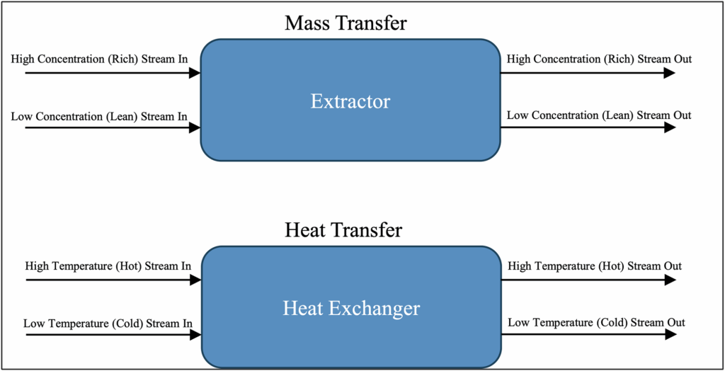
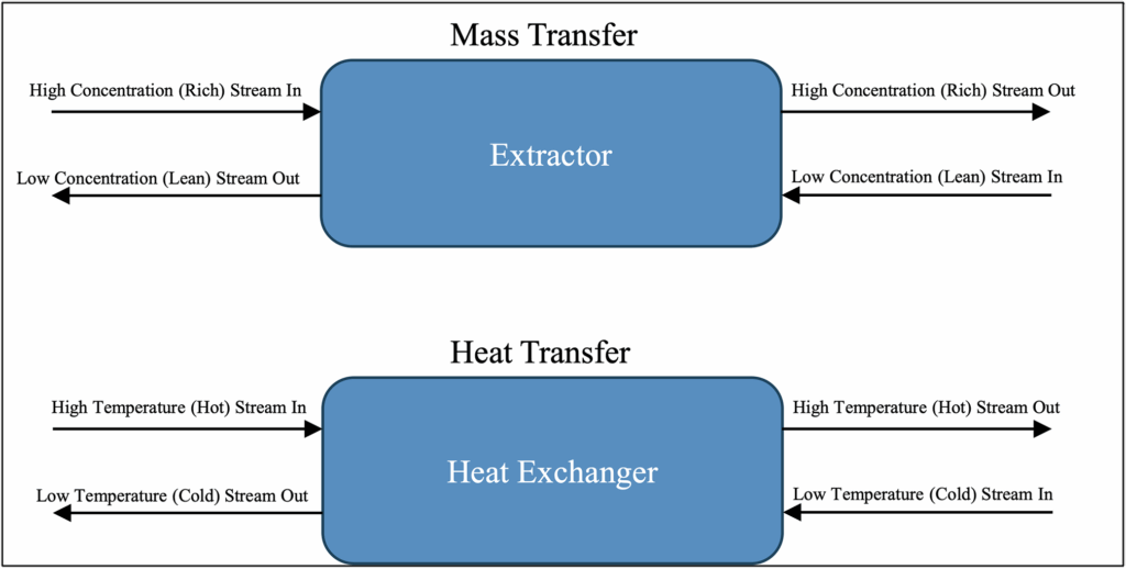
– Counter-Current Equipment Configurations: In counter-current equipment configurations, the streams enter opposite sides of the equipment and flow through the equipment in the opposite direction, as shown below in Figure 2. Counter-current configurations are typically more efficient than co-current configurations because they exhibit larger average concentration (mass transfer) and temperature (energy transfer) differences between the streams throughout the equipment.
Figure 2: Counter-Current Configurations
1 “Unit operation,” Wikipedia, accessed November 23, 2025, https://en.wikipedia.org/wiki/Unit_operation.
2 For additional information, see James N. Tilton, “Fluid and Particle Dynamics,” in Perry’s Chemical Engineer’s Handbook Seventh Edition, ed. Don W. Green (McGraw-Hill, 1997), 6-1 – 6-54.
3 For additional information, see Meherwan P. Boyce, “Transport and Storage of Fluids,” in Perry’s Chemical Engineer’s Handbook Seventh Edition, ed. Don W. Green (McGraw-Hill, 1997), 10-1 – 10-152.
4 For additional information, see James G. Knudsen, et. al., “Heat and Mass Transfer,” in Perry’s Chemical Engineer’s Handbook Seventh Edition, ed. Don W. Green (McGraw-Hill, 1997) 5-1 – 5-79.
5 For additional information, see Richard L. Shilling, et. al., “Heat-Transfer Equipment,” in Perry’s Chemical Engineer’s Handbook Seventh Edition, ed. Don W. Green (McGraw-Hill, 1997) 11-1 – 11-118.
6 For additional information, see Knudsen, et. al. “Heat and Mass Transfer.”
7 For additional information, see James R. Fair, et. al., “Gas Absorption and Gas-Liquid System Design,” in Perry’s Chemical Engineer’s Handbook Seventh Edition, ed. Don W. Green (McGraw-Hill, 1997) 14-1 – 14-98.
8 For additional information, see Lanny A. Robbins and Roger W. Cusack, “Liquid-Liquid Extraction Operations and Equipment,” in Perry’s Chemical Engineer’s Handbook Seventh Edition, ed. Don W. Green (McGraw-Hill, 1997) 15-1 – 15-47.
9 For additional information, see Shilling, et. al., “Heat-Transfer Equipment.”
10 For additional information, see Kalanadh V.S. Sastry, et. al., “Solid-Solid Operations and Equipment,” in Perry’s Chemical Engineer’s Handbook Seventh Edition, ed. Don W. Green (McGraw-Hill, 1997) 19-1 – 19-65.
11 For additional information, see Richard H. Snow, et. al., “Size Reduction and Size Enlargement,” in Perry’s Chemical Engineer’s Handbook Seventh Edition, ed. Don W. Green (McGraw-Hill, 1997) 20-1 – 20-89.
12 For additional information, see Stanley M. Walas, “Chemical Reactors,” in Perry’s Chemical Engineer’s Handbook Seventh Edition, ed. Don W. Green (McGraw-Hill, 1997) 23-1 – 23-61.
13 For additional information, see J.D. Seader, et. al., “Distillation,” in Perry’s Chemical Engineer’s Handbook Seventh Edition, ed. Don W. Green (McGraw-Hill, 1997) 13-1 – 13-108.
ADDITIONAL RESOURCES

Blog
Discover industry insights on construction disputes and claims, project management, risk analysis, and more.
MORE

Articles
Articles by our engineering and construction claims experts cover topics ranging from acceleration to why claims occur.
MORE

Publications
We are committed to sharing industry knowledge through publication of our books and presentations.
MORE
RECOMMENDED READS
Project and Construction Management Terminology
This post is part of a series defining industry terminology. This post addresses project and construction management.
READ
A Tale of Two Claims: Same Contract, Two Fates
The success of a claim often hinges not on what happened in the field, but how it was documented, analyzed, and communicated.
READ
The Role and Benefit of a Consultant in a Construction Project: Part 1
This is the first blog post in a two-part series on the role and benefit of a construction consultant.
READ