
January 9, 2023
Overview of CO2 Capture Technology
This is the final post in a six-part series that discusses carbon capture, utilization, and sequestration. The series covers topics including industry background; market overview and drivers; past, current, and planned carbon capture projects; and overviews of typical CO2 capture technologies.
This post provides overviews of typical carbon capture, utilization, and sequestration (CCUS) technologies. Specifically, this post discusses the typical processes employed for post-combustion carbon dioxide (CO2) capture and direct air capture (DAC).
In post-combustion carbon capture, which is typically employed in the power generation sector, CO2 is captured from flue gas streams that result from the combustion of fossil fuels. These flue gases contain between 3 and 15% CO2 by volume,1 with flue gases from natural gas-fired power plants exhibiting CO2 concentrations at the lower end of the range and flue gases from coal-fired power plants exhibiting CO2 concentrations at the higher end of the range. The captured CO2 is then compressed to its supercritical (SC) state for use in enhanced oil recovery (EOR) operations and/or for long-term sequestration.
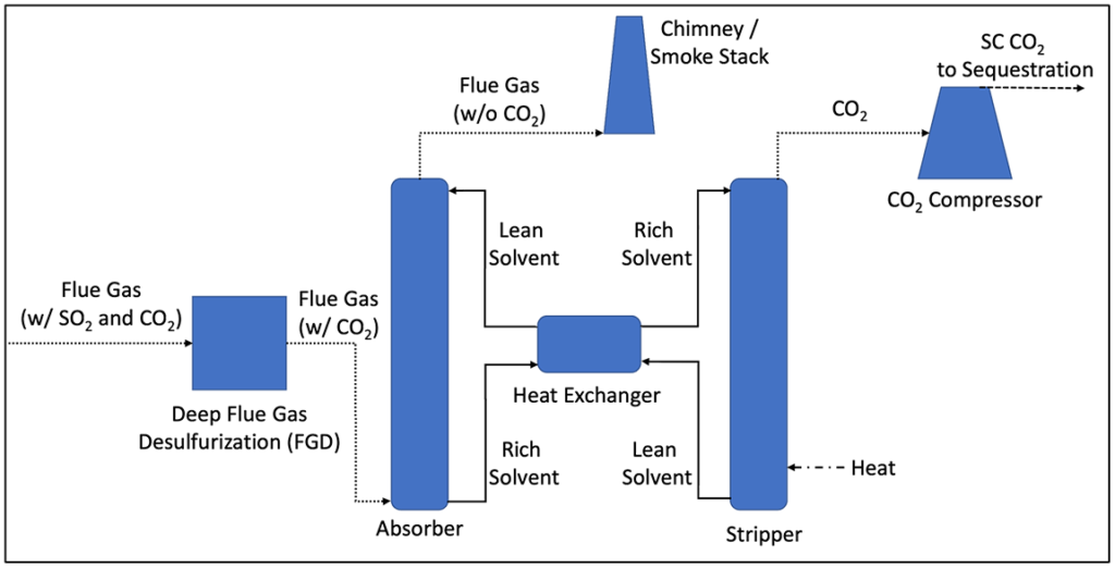
Figure 1 below is a simplified process flow diagram for a typical post-combustion CCUS system. The system is based on absorption of CO2 from the flue gas into a liquid solvent, via chemical reaction and the subsequent stripping of captured CO2 to regenerate the solvent through the addition of heat. Because the solvent also captures sulfur dioxide (SO2), which usually cannot be stripped from the solvent once it is captured, SO2 concentrations entering the CO2 absorber must be very low to prevent premature deactivation of the solvent. The primary unit operations utilized in a typical post-combustion CO2 capture process are as follows:
- Deep Flue Gas Desulfurization (FGD): SO2 is captured from the incoming flue gas using gas-liquid absorption. Very low SO2 concentrations are usually required prior to the CO2 absorber, potentially as low as 10 parts per million by volume (ppmv), dependent on the solvent.2 Although most coal-fired power generation stations in the U.S. are equipped with FGD systems to mitigate SO2 emissions, the existing FGD process may not meet the aggressive SO2 removal requirement prior to the CO2 absorber, potentially requiring the retrofit of a polishing scrubber for SO2. SO2 concentrations in flue gas from natural gas-fired power plants are inherently low.
- Carbon Capture Absorber: Based on gas-liquid absorption, captures CO2 from the incoming flue gas into a liquid solvent, which is typically amine-based. Solvent low in CO2 concentration entering the absorber is referred to as “lean” while solvent with higher CO2 concentration leaving the absorber is referred to as “rich.” CO2 capture rate targets are most commonly on the order of 90%–95%. The flue gas leaving the absorber is low in CO2 concentration and is sent out the stack to the atmosphere.
- Heat Exchanger: Transfers heat from the lean solvent leaving the CO2 stripper to the rich solvent entering the stripper, to conserve energy.
- Carbon Dioxide Stripper: Regenerates the solvent by stripping captured CO2 out of the rich solvent via the addition of heat. The amount of heat required is significant and can be a major contributor to the overall parasitic power draw on the power plant by the CO2 capture system. Lean solvent leaving the stripper is sent back through the heat exchanger to the absorber, completing the closed-loop absorption process.
- CO2 Compressor: Compresses the CO2 stream leaving the stripper to its supercritical state, to a final pressure on the order of 1,100 psi or greater. The supercritical CO2 can then be transported via pipeline for use in EOR or for underground sequestration.
Figure 1: Simplified Post-Combustion CCUS Flow Diagram
In DAC systems, CO2 is captured directly from the atmosphere, which is approximately 420 ppmv, or 0.04%, CO2. The captured CO2 is then typically compressed to its supercritical state for use in EOR operations and/or for long-term sequestration.
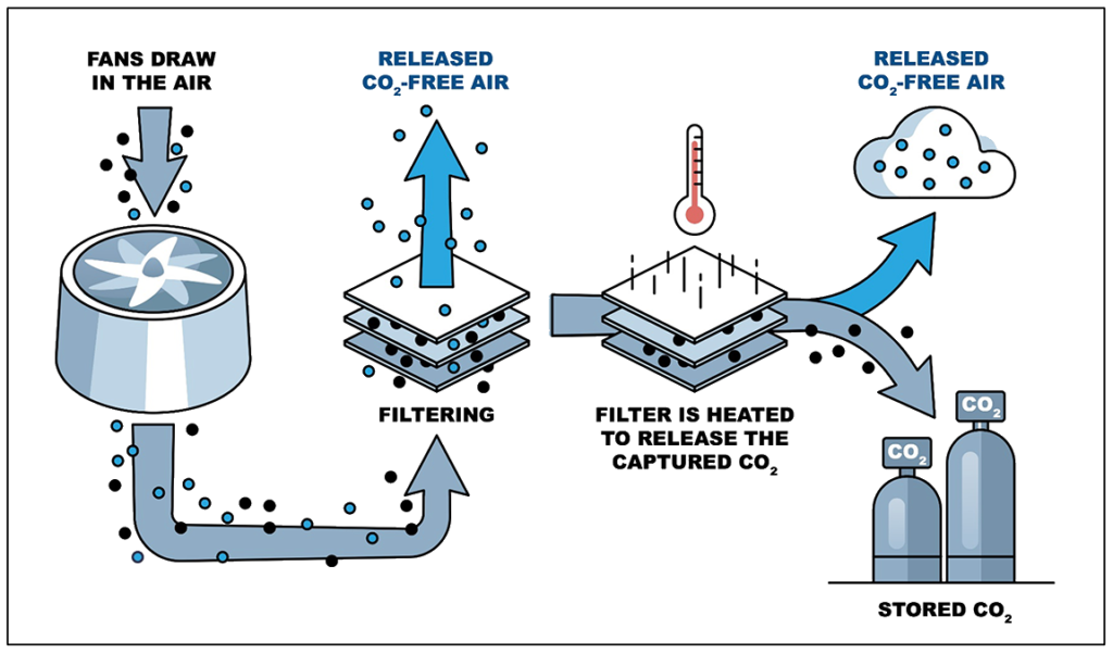
Figure 2 below is a simplified process flow diagram for a typical DAC system. The DAC can be either liquid-based, where the CO2 is absorbed into a liquid solvent through chemical reaction, or solid-based, where the CO2 is adsorbed onto a solid sorbent filter that reacts with and binds the CO2.3 The unit operations utilized in the typical DAC process are as follows:4
- Liquid-Based DAC:
a. A fan draws air into the DAC absorber unit.
b. The CO2 in the air stream is absorbed into a liquid solvent, which in the case of DAC is usually a strong basic hydroxide solution. CO2-free air is released back to the atmosphere.
c. The liquid solvent leaving the absorber unit goes through an anionic exchange to regenerate the liquid solvent and precipitate out the captured CO2 as a solid carbonate. The regenerated liquid is sent back to the absorber, completing the closed-loop absorption process. Because the regeneration of the liquid solvent occurs outside of the absorber unit, the absorption process can be run continuously.
d. In a separate regeneration process, the precipitated carbonate solids are regenerated, typically using heat and lime, to off-gas the CO2, which is collected and subsequently compressed to supercritical CO2 for use in EOR and/or for sequestration.
- Solid-Based DAC:
a. A fan draws air into the DAC adsorption unit.
b. The CO2 in the air stream is adsorbed onto a solid sorbent, or filter. CO2-free air is released back to the atmosphere.
c. When the solid adsorbent is saturated with CO2, it must be taken off-line for regeneration. Thus, the solid-based DAC process runs in batch mode, whereas the liquid-based DAC process described above is capable of continuous operation.
d. Regeneration is accomplished under vacuum using steam to heat the solid adsorbent to its regeneration temperature. The released CO2 is collected and subsequently compressed to supercritical CO2 for use in EOR and/or for sequestration.
Figure 2: Simplified Carbon Direct Air Capture Flow Diagram
1 David, E., V. Stanciu, C. Sandru, A. Armeanu, and V. Niculescu, “Exhaust gas treatment technologies for pollutant emission abatement from fossil fuel power plants.” WIT Transactions on Ecology and the Environment, Vol. 102, 2007. Accessed November 17, 2022. https://www.witpress.com/Secure/elibrary/papers/SDP07/SDP07088FU2.pdf.
2 Puxty, Graeme, Steven Chiao-Chien Wei, Paul Feron, Erik Meuleman, Yaser Beyad, Robert Burns, and Marcel Maeder, “A Novel Process Concept for the Capture of CO2 and SO2 using a Single Solvent and Column.” Energy Procedia, Vol. 63 (2014), pp. 703–714. Accessed 19 December 2022. https://www.sciencedirect.com/science/article/pii/S1876610214018931.
3 Paleja, Ameya, “The Japanese carbon capture method is 99 percent efficient and twice as fast.” Interesting Engineering, 30 May 2022. Accessed 19 December 2022. https://interestingengineering.com/innovation/direct-carbon-capture-99-percent-efficient.
4 McQueen, Noah, Katherine Vaz Gomes, Colin McCormick, Katherine Blumanthal, Maxwell Pisciotta, and Jennifer Wilcox, “A review of direct air capture (DAC): scaling up commercial technologies and innovating for the future.” Progress in Energy 3, 16 April 2021. Accessed 19 December 2022. https://iopscience.iop.org/article/10.1088/2516-1083/abf1ce.
ADDITIONAL RESOURCES

Blog
Discover industry insights on construction disputes and claims, project management, risk analysis, and more.
MORE

Articles
Articles by our engineering and construction claims experts cover topics ranging from acceleration to why claims occur.
MORE

Publications
We are committed to sharing industry knowledge through publication of our books and presentations.
MORE
Recommended Reads
Carbon Capture – A Capital-Intensive Technology with Large Growth Potential
This is the first post in a six-part series that discusses carbon capture, utilization, and sequestration.
READ
Overview of Carbon Capture, Utilization, and Sequestration Projects: Post-Combustion Capture
This is the second post in a six-part series that discusses carbon capture, utilization, and sequestration.
READ
Overview of Carbon Capture, Utilization, and Sequestration Projects: Direct Air Capture
This is the third post in a six-part series that discusses carbon capture, utilization, and sequestration.
READ